How to make your dashboard signal lights independent
I have a theory that Karmann wanted to make the Ghia with independently flashing in-dash signal lights. That's why there are two in the clock. However, that idea never materialized because the folks at VW didn't fulfill their end of the bargain by making it possible for the lights to flash independently.
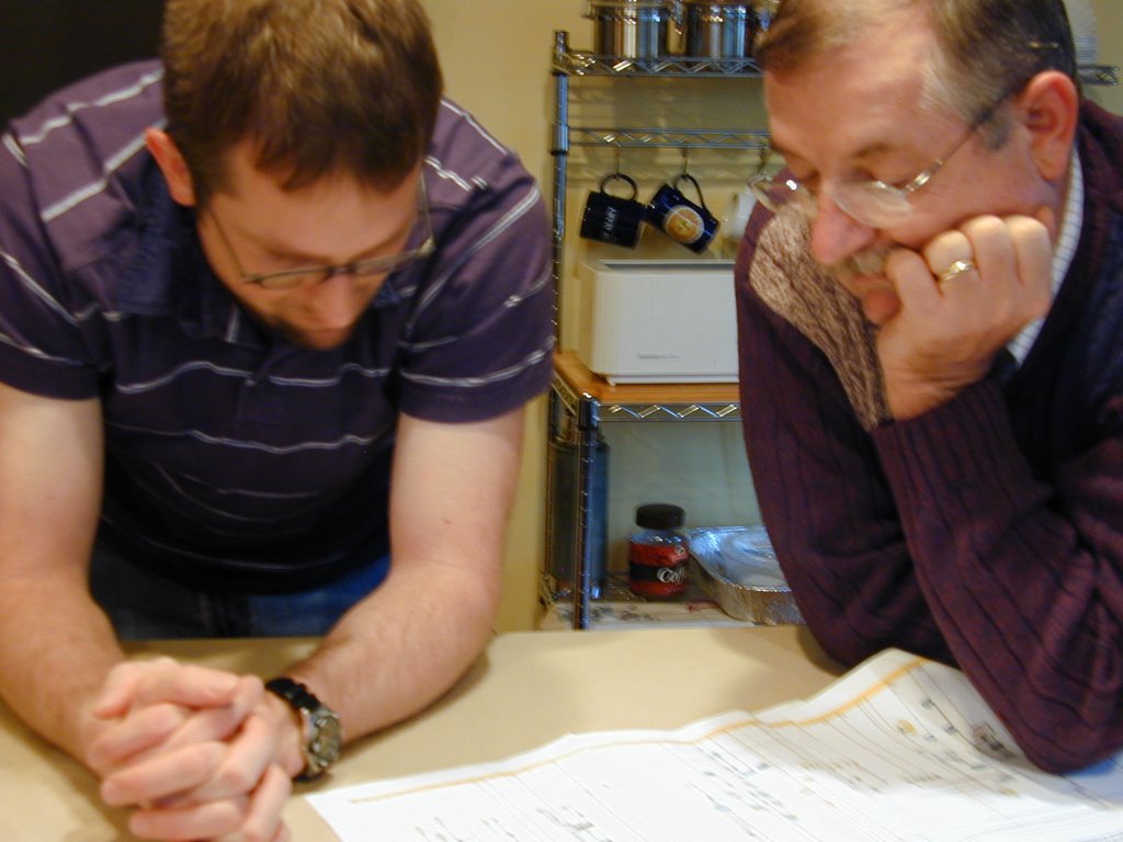
But, Dad and I just got his '73 vert's signal indicator lights to flash in accord with which direction you're signaling. Here's how we did it:
We started by studying the hell out of the wiring diagram. And those of you out there familiar with it know that it begs to have the hell studied out of it if you hope to get anywhere. But, to give you a newfound appreciation for the complexity of this diagram it took myself (a Web page developer), my dad (a professor of Management Information Systems who last year finished his dissertation on artificial intelligence) and my grandpa (a retired chemistry professor who recently published a book on Valence Bonding) an entire afternoon to make sense of just the turn signal wiring.

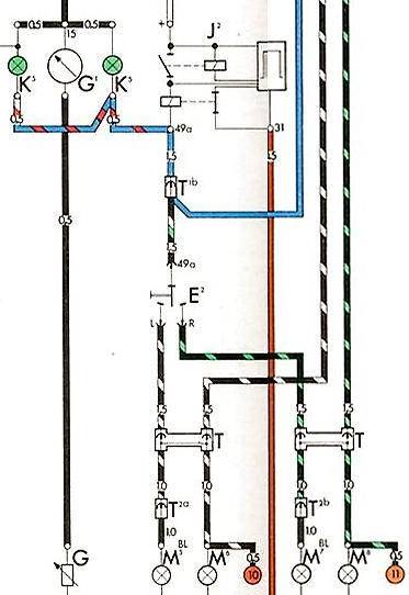
Here's a screenshot of the original turn signal wiring:

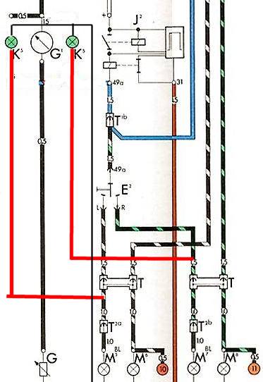
And here's how we modified it. The key to the new wires is the usual red=pos black=ground:

As you can see (take your time if you need) it really is as simple as disconnecting the dash indicators from the flasher relay and hooking them up directly to the exterior signal light wires. We, of course, ran into some sticky spots.
The first test we did was to just hook a test wire up from the signal wire to the small male terminal on the bulb housing. It proved at first that you could, indeed, get the bulbs to flash in correspondence with the exterior lights. However, the interior lights would stay on solid when you weren't signaling.
This was because the wire was essentially acting as a ground for the interior bulbs, grounding it through the exterior lights themselves. But, when you did signal the bulbs did blink. So, we just needed to figure out how to keep them from coming on when the signals weren't blinking.
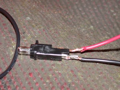
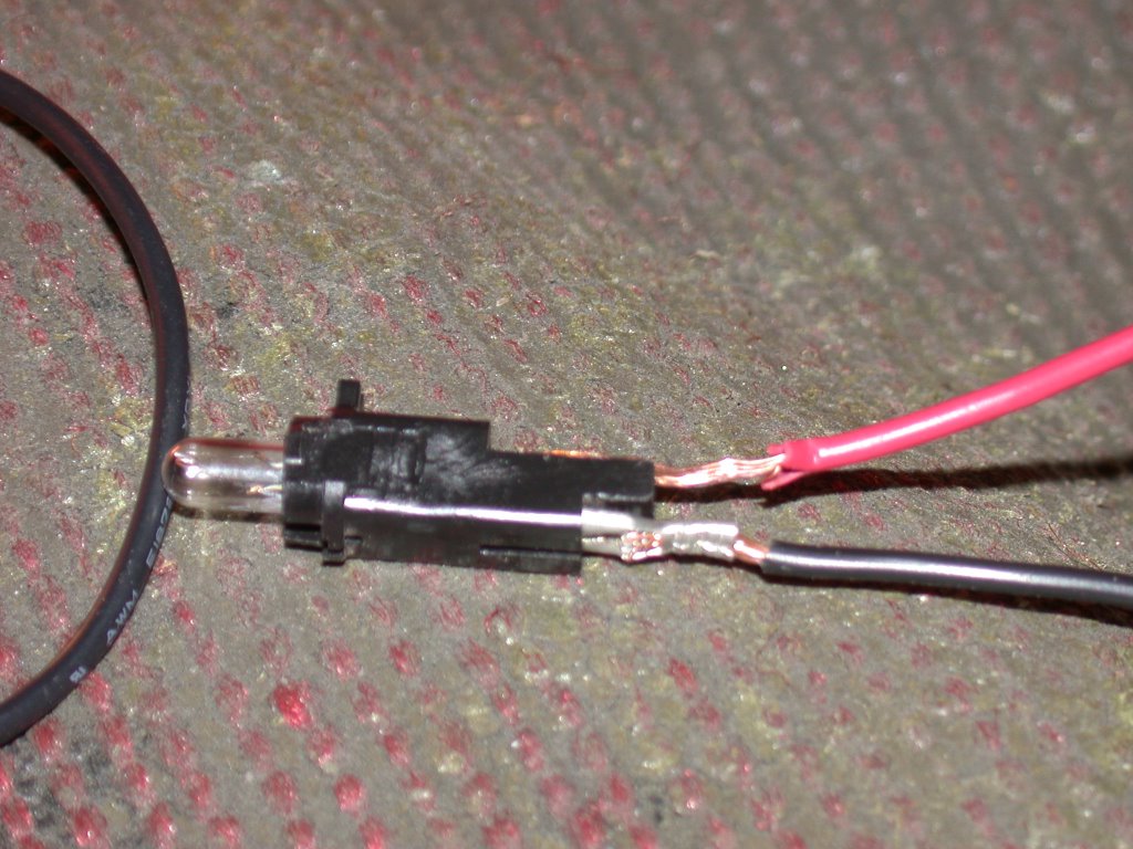
The trick was to keep the bulbs from getting their positive connection from the clock housing. There's a metal tab next to the light bulb that makes that connection. We snipped that tab off and then soldered a wire up to the other end of that single piece of brass, then we had control over where positive and negative were coming from.
That was the key, it turns out, and the rest of it was a simple matter of using the exterior signal wires as positive and then another wire for ground. Easy! Well, except for the three hours of swearing Dad endured soldering together tiny brass fittings onto 18 gauge wire. Here's the modified bulb housing:
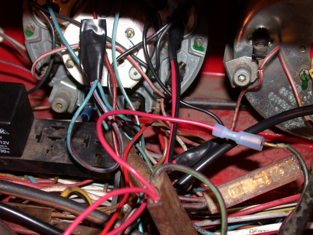
And here's a pictoral overview of the wiring for further reference:

But, Dad and I just got his '73 vert's signal indicator lights to flash in accord with which direction you're signaling. Here's how we did it:
We started by studying the hell out of the wiring diagram. And those of you out there familiar with it know that it begs to have the hell studied out of it if you hope to get anywhere. But, to give you a newfound appreciation for the complexity of this diagram it took myself (a Web page developer), my dad (a professor of Management Information Systems who last year finished his dissertation on artificial intelligence) and my grandpa (a retired chemistry professor who recently published a book on Valence Bonding) an entire afternoon to make sense of just the turn signal wiring.
Here's a screenshot of the original turn signal wiring:
And here's how we modified it. The key to the new wires is the usual red=pos black=ground:
As you can see (take your time if you need) it really is as simple as disconnecting the dash indicators from the flasher relay and hooking them up directly to the exterior signal light wires. We, of course, ran into some sticky spots.
The first test we did was to just hook a test wire up from the signal wire to the small male terminal on the bulb housing. It proved at first that you could, indeed, get the bulbs to flash in correspondence with the exterior lights. However, the interior lights would stay on solid when you weren't signaling.
This was because the wire was essentially acting as a ground for the interior bulbs, grounding it through the exterior lights themselves. But, when you did signal the bulbs did blink. So, we just needed to figure out how to keep them from coming on when the signals weren't blinking.
The trick was to keep the bulbs from getting their positive connection from the clock housing. There's a metal tab next to the light bulb that makes that connection. We snipped that tab off and then soldered a wire up to the other end of that single piece of brass, then we had control over where positive and negative were coming from.
That was the key, it turns out, and the rest of it was a simple matter of using the exterior signal wires as positive and then another wire for ground. Easy! Well, except for the three hours of swearing Dad endured soldering together tiny brass fittings onto 18 gauge wire. Here's the modified bulb housing:
And here's a pictoral overview of the wiring for further reference:
posted by Chris Druckenmiller at 4:01 PM
![]()


0 Comments:
Post a Comment
<< Home